
CloudBridge® Connector interoperability – F5 BIG-IP
You can configure a CloudBridge Connector tunnel between a NetScaler appliance and a F5 BIG-IP appliance to connect two datacenters or extend your network to a cloud provider. The NetScaler appliance and the F5 BIG-IP appliance form the end points of the CloudBridge Connector tunnel and are called peers.
Related information
Example of a CloudBridge Connector tunnel configuration
As an illustration of the traffic flow in a CloudBridge Connector tunnel, consider an example in which a CloudBridge Connector tunnel is set up between the following devices:
-
NetScaler appliance NS_Appliance-1 in a datacenter designated as Datacenter-1
-
F5 BIG-IP appliance F5-BIG-IP-Appliance-1 in a datacenter designated as Datacenter-2
NS_Appliance-1 and F5-BIG-IP-Appliance-1 enable communication between private networks in Datacenter-1 and Datacenter-2 through the CloudBridge Connector tunnel. In the example, NS_Appliance-1 and F5-BIG-IP-Appliance-1 enable communication between client CL1 in Datacenter-1 and server S1 in Datacenter-2 through the CloudBridge Connector tunnel. Client CL1 and server S1 are on different private networks.
On NS_Appliance-1, the CloudBridge Connector tunnel configuration includes IPSec profile entity NS_F5-BIG-IP_IPSec_Profile, CloudBridge Connector tunnel entity NS_F5-BIG-IP_Tunnel, and policy based routing (PBR) entity NS_F5-BIG-IP_Pbr.
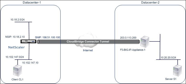
For more information, refer to F5 big IP pdf.
Points to consider for a CloudBridge Connector tunnel configuration
-
The NetScaler appliance is UP and running, is connected to the Internet, and is also connected to the private subnets whose traffic is to be protected over the CloudBridge Connector tunnel.
-
The F5 BIG-IP appliance is UP and running, is connected to the Internet, and is also connected to the private subnets whose traffic is to be protected over the CloudBridge Connector tunnel.
-
The following IPSec settings are supported for a CloudBridge Connector tunnel between a NetScaler appliance and an F5 BIG-IP appliance.
-
IPSec mode: Tunnel mode
-
IKE version: Version 1
-
IKE authentication method: Pre-Shared Key
-
IKE encryption algorithm: AES
-
IKE hash algorithm: HMAC SHA1
-
ESP encryption algorithm: AES
-
ESP hash algorithm: HMAC SHA1
-
-
You must specify the same IPSec settings on the NetScaler appliance and the F5 BIG-IP appliance at the two ends of the CloudBridge Connector tunnel.
-
NetScaler provides a common parameter (in IPSec profiles) for specifying an IKE hash algorithm and an ESP hash algorithm. It also provides another common parameter for specifying an IKE encryption algorithm and an ESP encryption algorithm. Therefore, in the F5 BIG-IP appliance, you must specify the same hash algorithm and same encryption algorithm in IKE (phase 1 configuration) and ESP (phase 2 configuration).
-
You must configure the firewall at the NetScaler end and F5 BIG-IP end to allow the following.
-
Any UDP packets for port 500
-
Any UDP packets for port 4500
-
Any ESP (IP protocol number 50) packets
-
Configuring F5 BIG-IP for the CloudBridge Connector tunnel
To configure a CloudBridge connector tunnel between a NetScaler appliance and an F5 BIG-IP appliance, perform the following tasks on the F5 BIG-IP appliance:
-
Create a forwarding virtual server for IPsec. A forwarding virtual server intercepts IP traffic for the IPsec tunnel.
-
Create an IKE peer. An IKE peer specifies the local and remote IPsec tunnel endpoints. It also specifies algorithms and credentials to be used for IPsec IKE phase 1.
-
Create a custom IPsec policy. A policy specifies the IPSec protocol (ESP) and the mode (tunnel) to be used for forming the IPsec tunnel. It also specifies the algorithms and security parameters to be used for IKE IPsec phase 2.
-
Create a bidirectional IPsec traffic selector. A traffic selector specifies the F5 BIG-IP side and NetScaler side subnets whose IP traffic is to be traversed through the IPsec tunnel.
The procedures for configuring IPsec VPN (CloudBridge Connector tunnel) on an F5 BIG-IP appliance might change over time, depending on the F5 release cycle. Citrix® recommends that you follow the official F5 BIG-IP documentation for configuring IPSec VPN tunnels, at:
<https://f5.com>
To create a forwarding virtual server for IPsec by using the F5 BIG-IP GUI
-
On the Main tab, click Local Traffic > Virtual Servers, and then click Create.
-
On New Virtual Server List screen, set the following parameters:
-
Name. Type a unique name for the virtual server.
-
Type. Select Forwarding (IP).
-
Destination Address. Type a wildcard network address in CIDR format, for example, 0.0.0.0/0 for IPv4 to accept any traffic.
-
Service Port. Select All Ports from the list.
-
Protocol list. Select All Protocols from the list.
-
VLAN and Tunnel Traffic. Retain the default selection, All VLANs and Tunnels.
-
-
Click Finished.
To create a custom IPsec policy by using the F5 BIG-IP GUI
-
On the Main tab, click Network > IPsec > IPsec Policies, and then click Create.
-
On the New Policy screen, set the following parameters:
-
Name. Type a unique name for the policy.
-
IPsec Protocol. Retain the default selection, ESP.
-
Mode. Select Tunnel. The screen refreshes to show additional related settings.
-
Tunnel Local Address. Type the local IPsec tunnel endpoint IP address (Configured on the F5 BIG-IP appliance).
-
Tunnel Remote Address. Type the remote IPsec tunnel endpoint IP address (Configured on the NetScaler appliance).
-
-
For the IKE Phase 2 parameters, retain the default values, or select the options that are appropriate for your deployment.
-
Click Finished.
To create a bidirectional IPsec traffic selector by using the F5 BIG-IP GUI
-
On the Main tab, click Network > IPsec > Traffic Selectors, and then click Create.
-
On the New Traffic Selector screen, set the following parameters:
-
Name. Type a unique name for the traffic selector.
-
Order. Retain the default value (First). This setting specifies the order in which the traffic selector appears on the Traffic Selector List screen.
-
-
From the Configuration list, select Advanced, and set the following parameters:
-
Source IP Address. Click Host or Network, and in Address field, type the address of the F5 BIG-IP side subnet whose traffic is to be protected over the IPsec tunnel.
-
Source Port. Select * All Ports.
-
Destination IP Address. Click Host, and in the Address field, type the address of the NetScaler side subnet whose traffic is to be protected over the IPsec tunnel.
-
Destination Port. Select * All Ports.
-
Protocol. Select * All Protocols.
-
Direction. Select Both.
-
Action. Select Protect. The IPsec Policy Name setting appears.
-
IPsec Policy Name. Select the name of the custom IPsec policy that you created.
-
-
Click Finished.
Configuring the NetScaler appliance for the CloudBridge Connector tunnel
To configure a CloudBridge Connector tunnel between a NetScaler appliance and a F5 BIG-IP appliance, perform the following tasks on the NetScaler appliance. You can use either the NetScaler command line or the NetScaler graphical user interface (GUI):
-
Create an IPSec profile. An IPSec profile entity specifies the IPSec protocol parameters, such as IKE version, encryption algorithm, hash algorithm, and authentication method to be used by the IPSec protocol in the CloudBridge Connector tunnel.
-
Create an IP tunnel that uses IPSec protocol, and associate the IPSec profile with it. An IP tunnel specifies the local IP address (CloudBridge Connector tunnel end point IP address (of type SNIP) configured on the NetScaler appliance), remote IP address (CloudBridge Connector tunnel endpoint IP address configured on the F5 BIG-IP appliance), protocol (IPSec) used to set up the CloudBridge Connector tunnel, and an IPSec profile entity. The created IP tunnel entity is also called the CloudBridge Connector tunnel entity.
-
Create a PBR rule and associate it with the IP tunnel. A PBR entity specifies a set of rules and an IP tunnel (CloudBridge Connector tunnel) entity. The source IP address range and the destination IP address range are the conditions for the PBR entity. Set the source IP address range to specify the NetScaler-side subnet whose traffic is to be protected over the tunnel, and set the destination IP address range to specify the F5 BIG-IP side subnet whose traffic is to be protected over the tunnel.
To create an IPSEC profile by using the NetScaler command line
At the command prompt, type:
-
add ipsec profile <name> -psk <string> -ikeVersion v1 -encAlgo AES -hashAlgo HMAC_SHA1 -perfectForwardSecrecyENABLE -
show ipsec profile** <name>
To create an IPSEC tunnel and bind the IPSEC profile to it by using the NetScaler command line
At the command prompt, type:
-
add ipTunnel <name> <remote> <remoteSubnetMask> <local> -protocol IPSEC –ipsecProfileName <string> -
show ipTunnel <name>
To create a PBR rule and bind the IPSEC tunnel to it by using the NetScaler command line
At the command prompt, type:
-
add pbr <pbrName> ALLOW –srcIP <subnet-range> -destIP <subnet-range> -ipTunnel <tunnelName> -
apply pbrs -
show pbr <pbrName>
To create an IPSEC profile by using the GUI
-
Navigate to System > CloudBridge Connector > IPSecProfile.
-
In the details pane, click Add.
-
In the Add IPSec Profile page, set the following parameters:
-
Name
-
Encryption Algorithm
-
Hash Algorithm
-
IKE Protocol Version
-
-
Configure the IPSec authentication method to be used by the two CloudBridge Connector tunnel peers to mutually authenticate: Select the Pre-shared key authentication method and set the Pre-Shared Key Exists parameter.
-
Click Create, and then click Close.
To create an IP tunnel and bind the IPSEC profile to it by using the GUI
-
Navigate to System > CloudBridge Connector > IP Tunnels.
-
On the IPv4 Tunnels tab, click Add.
-
In the Add IP Tunnel page, set the following parameters:
-
Name
-
Remote IP
-
Remote Mask
-
Local IP Type (In the Local IP Type drop-down list, select Subnet IP).
-
Local IP (All the configured IP addresses of the selected IP type are in the Local IP drop down list. Select the desired IP from the list.)
-
Protocol
-
IPSec Profile
-
-
Click Create, and then click Close.
To create a PBR rule and bind the IPSEC tunnel to it by using the GUI
-
Navigate to System > Network > PBR.
-
On the PBR tab, click Add.
-
In the Create PBR page, set the following parameters:
-
Name
-
Action
-
Next Hop Type (Select IP Tunnel)
-
IP Tunnel Name
-
Source IP Low
-
Source IP High
-
Destination IP Low
-
Destination IP High
-
-
Click Create, and then click Close.
The corresponding new CloudBridge Connector tunnel configuration on the NetScaler appliance appears in the GUI. The current status of the CloudBridge connector tunnel is shown in the Configured CloudBridge Connector pane. A green dot indicates that the tunnel is up. A red dot indicates that the tunnel is down.
The following commands create settings of NetScaler appliance NS_Appliance-1 in "Example of a CloudBridge Connector Configuration.:
    >  add ipsec profile NS_F5-BIG-IP_IPSec_Profile -psk  examplepresharedkey -ikeVersion v1 –encAlgo AES –hashalgo HMAC_SHA1 –lifetime 315360 -perfectForwardSecrecy ENABLE


     Done

     >  add iptunnel NS_F5-BIG-IP_Tunnel 203.0.113.200 255.255.255.255 198.51.100.100 –protocol IPSEC –ipsecProfileName NS_F5-BIG-IP_IPSec_Profile


     Done

     > add pbr NS_F5-BIG-IP_Pbr -srcIP 10.102.147.0-10.102.147.255 –destIP 10.20.0.0-10.20.255.255 –ipTunnel NS_F5-BIG-IP_Tunnel


     Done

     > apply pbrs


     Done
Monitoring the CloudBridge Connector tunnel
You can monitor the performance of CloudBridge Connector tunnels on a NetScaler appliance by using CloudBridge Connector tunnel statistical counters. For more information about displaying CloudBridge Connector tunnel statistics on a NetScaler appliance, see Monitoring CloudBridge Connector Tunnels.