
VXLAN
NetScaler appliances support Virtual eXtensible Local Area Networks (VXLANs). A VXLAN overlays Layer 2 networks onto a layer 3 infrastructure by encapsulating Layer-2 frames in UDP packets. Each overlay network is known as a VXLAN Segment and is identified by a unique 24-bit identifier called the VXLAN Network Identifier (VNI). Only network devices within the same VXLAN can communicate with each other.
VXLANs provide the same Ethernet Layer 2 network services that VLANs do, but with greater extensibility and flexibility. The two main benefits of using VXLANs are the following:
-
Higher scalability. Server virtualization and cloud computing architectures have dramatically increased the demand for isolated Layer 2 networks in a datacenter. The VLAN specification uses a 12-bit VLAN ID to identify a Layer 2 network, so you cannot scale beyond 4094 VLANs. That number can be inadequate when the requirement is for thousands of isolated Layer 2 networks. The 24-bit VNI accommodates up to 16 million VXLAN segments in the same administrative domain.
-
Higher flexibility. Because VXLAN carries Layer 2 data frames over Layer 3 packets, VXLANs extend L2 networks across different parts of a datacenter and across geographically separated datacenters. Applications that are hosted in different parts of a datacenter and in different datacenters but are part of the same VXLAN appear as one contiguous network.
Related information
How VXLANs Work
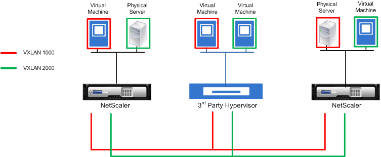
VXLAN Segments are created between VXLAN Tunnel End Points (VTEPs). VTEPs support the VXLAN protocol and perform VXLAN encapsulation and decapsulation. You can think of a VXLAN segment as a tunnel between two VTEPs, where one VTEP encapsulates a Layer2 frame with a UDP header and an IP header and sends it through the tunnel. The other VTEP receives and decapsulates the packet to get the Layer 2 frame. A NetScaler is one example of a VTEP. Other examples are third-party hypervisors, VXLAN aware virtual machines, and VXLAN capable switches.
The following illustration displays virtual machines and physical servers connected through VXLAN tunnels.
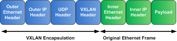
The following illustration displays the format of a VXLAN packet.
VXLANs on a NetScaler use a Layer 2 mechanism for sending broadcast, multicast, and unknown unicast frames. A VXLAN supports the following modes for sending these L2 frames.
-
Unicast mode: In this mode, you specify the IP addresses of VTEPs while configuring a VXLAN on a NetScaler. The NetScaler sends broadcast, multicast, and unknown unicast frames over Layer 3 to all VTEPs of this VXLAN.
-
Multicast mode: In this mode, you specify a multicast group IP address while configuring a VXLAN on a NetScaler. NetScalers do not support Internet Group Management Protocol (IGMP) protocol. NetScalers rely on the upstream router to join a multicast group, which shares a common multicast group IP address. The NetScaler sends broadcast, multicast, and unknown unicast frames over Layer 3 to the multicast group IP address of this VXLAN.
Similar to a Layer 2 bridge table, NetScalers maintain VXLAN mapping tables based on the inner and outer header of the received VXLAN packets. This table maps of remote host MAC addresses to VTEP IP addresses for a particular VXLAN. The NetScaler uses the VXLAN mapping table to look up the destination MAC address of a Layer 2 frame. If an entry for this MAC address is present in the VXLAN table, the NetScaler sends the Layer 2 frame over Layer 3, using the VXLAN protocol, to the mapped VTEP IP address specified in the mapping entry for a VXLAN.
Because VXLANs function similarly to VLANs, most of the NetScaler features that support VLAN as a classification parameter support VXLAN. These features include an optional VXLAN parameter setting, which specifies the VXLAN VNI.
In a high availability (HA) configuration, the VXLAN configuration is propagated or synchronized to the secondary node.
VXLAN Use Case: Load Balancing across Datacenters
To understand the VXLAN functionality of a NetScaler, consider an example in which Example Corp hosts a site at www.example.com. To ensure application availability, the site is hosted on three servers, S0, S1, and S2. A load balancing virtual server, LBVS, on NetScaler NS-ADC is used to load balance these servers. S0, S1, and S2 reside in datacenters DC0, DC1, and DC2, respectively. In DC0, server S0 is connected to NS-ADC.
S0 is a physical server, and S1 and S2 are virtual machines (VMs). S1 runs on virtualization host device Dev-VTEP-1 in datacenter DC1, and S2 runs on host device Dev-VTEP-2 in DC2. NS-ADC, Dev-VTEP-1, and Dev-VTEP-2 support the VXLAN protocol.
S0, S1, and S2 are part of the same private subnet, 192.0.1.0/24. S0, S1, and S2 be part of a common broadcast domain, VXLAN 9000 is configured on NS-ADC, Dev-VTEP-1, and Dev-VTEP-2. Servers S1 and S2 are made part of VXLAN9000 on Dev-VTEP-1 and Dev-VTEP-2, respectively.
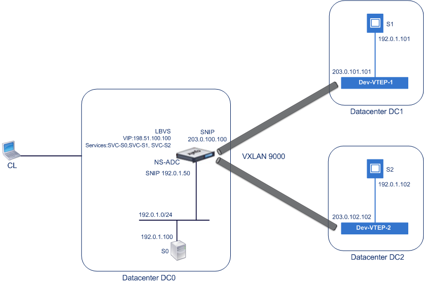
The following table lists the settings used in this example: VXLAN settings.
Services SVC-S0, SVC-S1, and SVC-S2 on NS-ADC represent S0, S1, and S2. As soon as these services are configured, NS-ADC broadcasts ARP requests for S0, S1, and S2 to resolve IP-to-MAC mapping. These ARP requests are also sent over VXLAN 9000 to Dev-VTEP-1 and Dev-VTEP-2.
Following is the traffic flow for resolving the ARP request for S2:
-
NS-ADC broadcasts an ARP request for S2 to resolve IP-to-MAC mapping. This packet has:
-
Sourced IP address = Subnet IP address SNIP-for-Servers (192.0.1.50)
-
Source MAC address = MAC address of the NS-ADC’s interface from which the packet is sent out = NS-MAC-1
-
-
NS-ADC prepares the ARP packet to be sent over the VXLAN 9000 by encapsulating the packet with following headers:
-
VXLAN header with an ID (VNI) of 9000
-
Standard UDP header, UDP checksum set to 0×0000, and destination port set to 4789.
-
-
NS-ADC sends the resulting encapsulated packet to Dev-VTEP-1 and Dev-VTEP-2 on VXLAN-9000. The encapsulated packet has:
-
Source IP address = SNIP-VTEP-0 (203.0.100.100).
-
-
Dev-VTEP-2 receives the UDP packet and decapsulates the UDP header, from which Dev-VTEP-2 learns that the packet is a VXLAN related packet. Dev-VTEP-2 then decapsulates the VXLAN header and learns the VXLAN ID of the packet. The resulting packet is the ARP request packet for S2, which is same as in step 1.
-
From the inner and outer header of the VXLAN packet, Dev-VTEP-2 makes an entry in its VXLAN mapping table that shows the mapping of MAC address (NS-MAC-1) and SNIP-VTEP-0 (203.0.100.100) for VXLAN9000.
-
Dev-VTEP-2 sends the ARP packet to S2. S2’s response packet reaches Dev-VTEP-2. Dev-VTEP-2 performs a lookup in its VXLAN mapping table and gets a match for the destination MAC address NS-MAC-1. The Dev-VTEP-2 now knows that NS-MAC-1 is reachable through SNIP-VTEP-0 (203.0.100.100) over VXLAN 9000.
-
S2 responds with its MAC address (MAC-S2). The ARP response packet has:
-
Destination IP address = Subnet IP address SNIP-for-Servers (192.0.1.50)
-
Destination MAC address = NS-MAC-1
-
-
S2’s response packet reaches Dev-VTEP-2. Dev-VTEP-2 performs a lookup in its VXLAN mapping table and gets a match for the destination MAC address NS-MAC-1. The Dev-VTEP-2 now knows that NS-MAC-1 is reachable through SNIP-VTEP-0 (203.0.100.100) over VXLAN 9000. Dev-VTEP-2 encapsulates the ARP response with VXLAN and UDP headers, and sends the resultant packet to SNIP-VTEP-0 (203.0.100.100) of NS-ADC.
-
NS-ADC on receiving the packet, decapsulates the packet by removing the VXLAN and UDP headers. The resultant packet is S2’s ARP response. NS-ADC updates it VXLAN mapping table for S2’s MAC address (MAC-S2) with Dev-VTEP-2’s IP address (203.0.102.102) for VXLAN 9000. NS-ADC also updates it ARP table for S2’s IP address (192.0.1.102) with S2’s MAC address (MAC-S2).
Following is the traffic flow for load balancing virtual server LBVS in this example:
-
Client CL sends a request packet to LBVS of NS-ADC. The request packet has:
-
Source IP address = IP address of client CL (198.51.100.90)
-
Destination IP address = IP address (VIP) of LBVS = 198.51.110.100
-
-
LBVS of NS-ADC receives the request packet, and its load balancing algorithm selects server S2 of datacenter DC2.
-
NS-ADC processes the request packet, changing its destination IP address to the IP address of S2 and its source IP address to one of the Subnet IP (SNIP) addresses configured on NS-ADC. The request packet has:
-
Source IP address = Subnet IP address on NS-ADC= SNIP-for-Servers (192.0.1.50)
-
Destination IP address = IP address of S2 (192.0.1.102)
-
-
NS-ADC finds a VXLAN mapping entry for S2 in its bridge table. This entry indicates that S2 is reachable through Dev-VTEP-2 over VXLAN 9000.
-
NS-ADC prepares the packet to be sent over the VXLAN 9000 by encapsulating the packet with following headers:
-
VXLAN header with an ID (VNI) of 9000
-
Standard UDP header, UDP checksum set to 0×0000, and destination port set to 4789.
-
-
NS-ADC sends the resulting encapsulated packet to Dev-VTEP-2. The request packet has:
-
Source IP address = SNIP address = SNIP-VTEP-0 (203.0.100.100)
-
Destination IP address = IP address of Dev-VTEP-2 (203.0.102.102)
-
-
Dev-VTEP-2 receives the UDP packet and decapsulates the UDP header, from which Dev-VTEP-2 learns that the packet is a VXLAN related packet. Dev-VTEP-2 then decapsulates the VXLAN header and learns the VXLAN ID of the packet. The resulting packet is the same packet as in step 3.
-
Dev-VTEP-2 then forwards the packet to S2.
-
S2 processes the request packet and sends the response to the SNIP address of NS-ADC. The response packet has:
-
Source IP address = IP address of S2 (192.0.1.102)
-
Destination IP address = Subnet IP address on NS-ADC= SNIP-for-Servers (192.0.1.50)
-
-
Dev-VTEP-2 encapsulates the response packet in the same way that NS-ADC encapsulated the request packet in steps 4 and 5. Dev-VTEP-2 then sends the encapsulated UDP packet to SNIP address SNIP-for-Servers (192.0.1.50) of NS-ADC.
-
NS-ADC, upon receiving the encapsulated UDP packet, decapsulates the packet by removing the UDP and VXLAN headers in the same way that Dev-VTEP-2 decapsulated the packet in step 7. The resultant packet is the same response packet as in step 9.
-
NS-ADC then uses the session table for load balancing virtual server LBVS, and forwards the response packet to client CL. The response packet has:
-
Source IP address = IP address of client CL (198.51.100.90)
-
Destination IP address = IP address (VIP) of LBVS (198.51.110.100)
-
Points to Consider for Configuring VXLANs
Consider the following points before configuring VXLANs on a NetScaler:
-
A maximum of 2048 VXLANs can be configured on a NetScaler.
-
VXLANs are not supported in a cluster.
-
Link-local IPv6 addresses cannot be configured for each VXLAN.
-
NetScalers do not support Internet Group Management Protocol (IGMP) protocol to form a multicast group. NetScalers rely on the IGMP protocol of its upstream router to join a multicast group, which share a common multicast group IP address. You can specify a multicast group IP address while creating VXLAN bridge table entries but the multicast group must be configured on the upstream router. The NetScaler sends broadcast, multicast, and unknown unicast frames over Layer 3 to the multicast group IP address of this VXLAN. The upstream router then forwards the packet to all the VTEPs that are part of the multicast group.
-
VXLAN encapsulation adds an overhead of 50 bytes to each packet:Outer Ethernet Header (14) + UDP header (8) + IP header (20) + VXLAN header (8) = 50 bytesTo avoid fragmentation and performance degradation, you must adjust the MTU settings of all network devices in a VXLAN pathway, including the VXLAN VTEP devices, to handle the 50 bytes of overhead in the VXLAN packets.Important: Jumbo frames are not supported on the NetScaler VPX virtual appliances, NetScaler SDX appliances, and NetScaler MPX 15000/17000 appliances. These appliances support an MTU size of only 1500 bytes and cannot be adjusted to handle the 50 bytes overhead of VXLAN packets. VXLAN traffic might be fragmented or suffer performance degradation, if one of these appliances is in the VXLAN pathway or acts as a VXLAN VTEP device.
-
On NetScaler SDX appliances, VLAN filtering does not work for VXLAN packets.
-
You cannot set a MTU value on a VXLAN.
-
You cannot bind interfaces to a VXLAN.
Configuration Steps
Configuring a VXLAN on a NetScaler appliance consists of the following tasks.
-
Add a VXLAN entity. Create a VXLAN entity uniquely identified by a positive integer, which is also called the VXLAN Network Identifier (VNI). In this step, you can also specify the destination UDP port of remote VTEP on which the VXLAN protocol is running. By default, the destination UDP port parameter is set to 4789 for the VXLAN entity. This UDP port setting must match the settings on all remote VTEPs for this VXLAN. You can also bind VLANs to this VXLAN. The traffic (which includes broadcasts, multicasts, unknown unicasts) of all bound VLANs are allowed over this VXLAN. If no VLANs are bound to the VXLAN, the NetScaler allows traffic of all VLANs, on this VXLAN, that are not part of any other VXLANs.
-
Bind the local VTEP IP address and to the VXLAN entity. Bind one of the configured SNIP address to the VXLAN to source outgoing VXLAN packets.
-
Add a bridgetable entry. Add a bridgetable entry specifying the VXLAN ID and the remote VTEP IP address for the VXLAN to be created.
-
(Optional) Bind different feature entities to the configured VXLAN. VXLANs function similarly to VLANs, most of the NetScaler features that support VLAN as a classification parameter also support VXLAN. These features include an optional VXLAN parameter setting, which specifies the VXLAN VNI.
-
(Optional) Display the VXLAN mapping table. Display the VXLAN mapping table, which includes mapping entries for remote host MAC address to VTEP IP address for a particular VXLAN. In other words, a VXLAN mapping states that a host is reachable through the VTEP on a particular VXLAN. The NetScaler learns VXLAN mappings and updates its mapping table from the VXLAN packets it receives. The NetScaler uses the VXLAN mapping table to lookup for the destination MAC address of a Layer 2 frame. If an entry for this MAC address is present in the VXLAN table, the NetScaler sends the Layer 2 frame over Layer 3, using the VXLAN protocol, to the mapped VTEP IP address specified in the mapping entry for a VXLAN.
CLI procedures
To add a VXLAN entity by using CLI:
At the command prompt, type
-
add vxlan \<id>
-
show vxlan\<id>
To bind the local VTEP IP address to the VXLAN by using CLI:
At the command prompt, type
-
bind vxlan \<id> -SrcIP \<IPaddress>
-
show vxlan \<id>
To add a bridgetable by using CLI:
At the command prompt, type
-
add bridgetable -mac \<macaddress> -vxlan \<ID> -vtep \<IPaddress>
-
show bridgetable
To display the VXLAN forwarding table by using the command line:
At the command prompt, type:
-
show bridgetable
GUI procedures
To add a VXLAN entity and bind a local VTEP IP address by using the GUI:
Navigate to System > Network > VXLANs, and add a new VXLAN entity or modify an existing VXLAN entity.
To add a bridgetable by using the GUI:
Navigate to System > Network > Bridge Table, set the following paramters while adding or modifying a VXLAN bridge table entry:
-
MAC
-
VTEP
-
VXLAN ID
To display the VXLAN forwarding table by using the GUI:
Navigate to System > Network > Bridge Table.
Example
 > add vxlan 9000
 Done
 > bind vxlan 9000 -srcIP 203.0.100.100

 Done
 > add bridgetable -mac 00:00:00:00:00:00 -vxlan 9000 -vtep 203.0.101.101

 Done
 > add bridgetable -mac 00:00:00:00:00:00 -vxlan 9000 -vtep 203.0.102.102

 Done
Support of IPv6 Dynamic Routing Protocols on VXLANs
The NetScaler appliance supports IPv6 dynamic routing protocols for VXLANs. You can configure various IPv6 Dynamic Routing protocols (for example, OSPFv3, RIPng, BGP) on VXLANs from the VTYSH command line. An option IPv6 Dynamic Routing Protocol has been added to VXLAN command set for enabling or disabling IPv6 dynamic routing protocols on a VXLAN. After enabling IPv6 dynamic routing protocols on a VXLAN, processes related to the IPv6 dynamic routing protocols are required to be started on the VXLAN by using the VTYSH command line.
To enable IPv6 Dynamic routing protocols on a VXLAN by using the CLI:
-
show vxlan
In the following sample configuration, VXLAN-9000 is created and has IPv6 dynamic routing protocols enabled on it. Then, using the VTYSH command line, process for the IPv6 OSPF protocol is started on the VXLAN.

 > add vxlan 9000 -ipv6DynamicRouting ENABLED

 Done
 > bind vxlan 9000 -srcIP 203.0.100.100

 Done
 > add bridgetable -mac 00:00:00:00:00:00 -vxlan 9000 -vtep 203.0.101.101

 Done
 > VTYSH
 NS# configure terminal
 NS(config)# ns IPv6-routing
 NS(config)# interface VXLAN-9000
 NS(config-if)# ipv6 router OSPF area 3
Extending VLANs from Multiple Enterprises to a Cloud using VXLAN-VLAN Maps
CloudBridge Connector tunnels is used to extend an enterprise's VLAN to a cloud. VLANs extended from multiple enterprises can have overlapping VLAN IDs. You can isolate each enterprise's VLANs, by mapping them to a unique VXLAN in the cloud. On a NetScaler appliance, which is the CloudBridge connector endpoint in the cloud, you can configure a VXLAN-VLAN map that links an enterprise's VLANs to a unique VXLAN in the cloud. VXLANs support VLAN tagging for extending multiple VLANs of an enterprise from CloudBridge Connector to the same VXLAN.
Perform the following tasks for extending VLANs of multiple enterprises to a cloud:
-
Create a VXLAN-VLAN map.
-
Bind the VXLAN-VLAN map to a network bridge based or PBR based CloudBridge Connector tunnel configuration on the NetScaler appliance on cloud.
-
(Optional) Enable VLAN tagging in a VXLAN configuration.
CLI procedures
To add a VXLAN-VLAN map by using the CLI:
-
add vxlanVlanMap \<name>
-
show vxlanVlanMap \<name>
To bind a VXLAN and VLANS to a VXLAN-VLAN map by using the CLI:
-
show vxlanVlanMap \<name>
To bind a VXLAN-VLAN map to a network bridge based CloudBridge® Connector tunnel by using the CLI:
At the command prompt, type one of the following sets of commands.
if adding a new network bridge:
-
show netbridge \<name>
if reconfiguring an existing network bridge:
-
show netbridge \<name>
To bind a VXLAN-VLAN map to a PBR based CloudBridge Connector tunnel by using the CLI:
At the command prompt, type one of the following sets of commands.
if adding a new PBR:
-
show pbr \<name>
if reconfiguring an existing PBR:
-
show pbr \<name>
To include VLAN tags in packets related to a VXLAN by using the CLI:
At the command prompt, type one of the following sets of commands.
if adding a new VXLAN:
-
add vxlan \<vnid> -vlanTag (ENABLED | DISABLED)
-
show vxlan \<vnid>
if reconfiguring an existing VXLAN:
-
set vxlan \<vnid> -vlanTag (ENABLED | DISABLED)
-
show vxlan \<vnid>
GUI procedures
To add a VXLAN-VLAN map by using the GUI:
Navigate to System > Network > VXLAN VLAN Map, add a VXLAN VLAN map.
To bind a VXLAN-VLAN map to a netbridge based CloudBridge Connector tunnel by using the GUI:
Navigate to System > CloudBridge Connector > Network Bridge, select a VXLAN-VLAN map from the VXLAN VLAN drop down list while adding a new network bridge, or reconfiguring an existing network bridge.
To bind a VXLAN-VLAN map to a PBR based CloudBridge Connector tunnel by by using the GUI:
Navigate to System > Network > PBRs, on the Policy Based Routing (PBRs) tab, select a VXLAN-VLAN map from the VXLAN VLAN drop down list while adding a new PBR, or reconfiguring an existing PBR.
To include VLAN tags in packets related to a VXLAN by using the GUI:
Navigate to System > Network > VXLANs, enable Inner VLAN Tagging while adding a new VXLAN, or reconfiguring an existing VXLAN.
> add vxlanVlanMap VXLANVLAN-DC1

 Done

 > bind vxlanvlanmap VXLANVLAN-DC1 -vxlan 3000 -vlan 3

 Done

 > bind vxlanvlanmap VXLANVLAN-DC1 -vxlan 3500 -vlan 4

 Done

 >add vxlanVlanMap VXLANVLAN-DC2

 Done

 > bind vxlanvlanmap VXLANVLAN-DC1 -vxlan 8000 -vlan 3 4

 Done

 > set pbr PBR-CBC-DC-1-CLOUD ALLOW  -ipTunnel  CBC-DC-1-CLOUD -vxlanVlanMap VXLANVLAN-DC1

 Done

 > set pbr PBR-CBC-DC-2-CLOUD ALLOW  -ipTunnel  CBC-DC-2-CLOUD -vxlanVlanMap VXLANVLAN-DC2

 Done