
Load balance RTSP servers
The NetScaler appliance can balance the load on RTSP servers to improve the performance of audio and video streams over networks. The following diagram describes the topology of a load balancing setup configured to load balance a group of RTSP servers.
Figure 1. Load Balancing Topology for RTSP
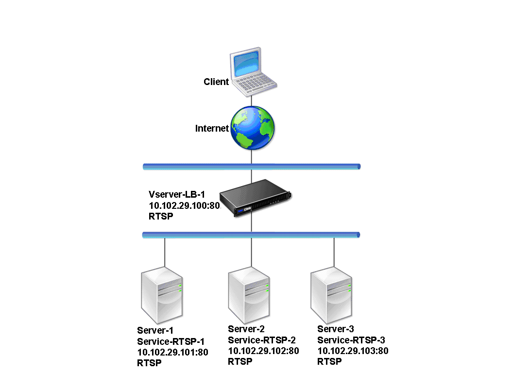
In the example, the services Service-RTSP-1, Service-RTSP-2, and Service-RTSP-3 are bound to the virtual server Vserver-LB-1. The following table lists the names and values of the example entities.
| Entity type | Name | IP address | Port | Protocol |
|---|---|---|---|---|
| Virtual Server | Vserver-LB-1 | 10.102.29.100 | 554 | RTSP |
| Services | Service-RTSP-1 | 10.102.29.101 | 554 | RTSP |
| Service-RTSP-2 | 10.102.29.102 | 554 | RTSP | |
| Service-RTSP-3 | 10.102.29.103 | 554 | RTSP | |
| Monitors | Monitor-RTSP-1 | None | 554 | RTSP |
The following diagram shows the load balancing entities used in the RTSP configuration.
Figure 2. Load Balancing RTSP Servers Entity Model
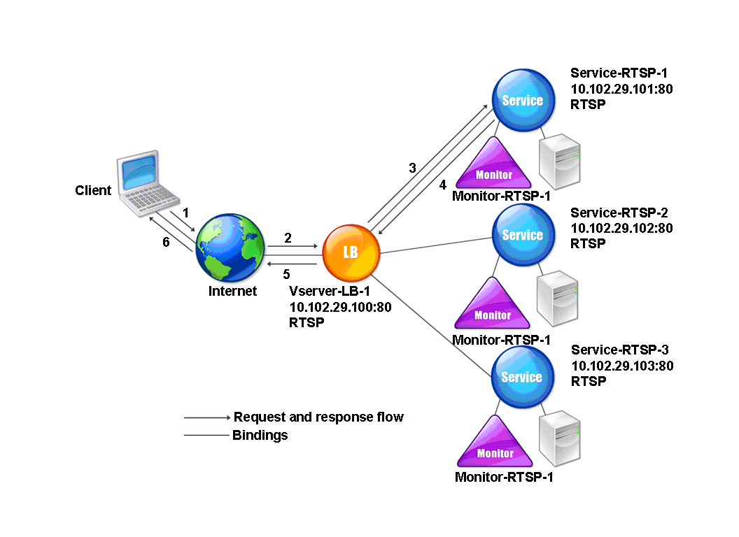
To configure a basic load balancing setup for RTSP servers, see Setting Up Basic Load Balancing. Create services and virtual servers of type RTSP. When you configure a basic load balancing setup, the default TCP-default monitor is bound to the services. To bind an RTSP monitor to these services, see Binding Monitors to Services. The following procedure describes how create a monitor that checks RTSP servers.
Related information
To configure RTSP monitors by using the CLI
At the command prompt, type:
add lb monitor <monitorName> <type>
Example:
add lb monitor Monitor-RTSP-1 RTSP
To configure RTSP monitors by using the GUI
Navigate to Traffic Management > Load Balancing > Monitors, and create a monitor of type RTSP.