
Install the hardware
Determining that the location where you plan to install your appliance meets the environmental standards and the server rack is in place according to the instructions. After you mount the appliance, you are ready to connect it to the network, to a power source, and to the console terminal that you will use for initial configuration. To complete the installation, you turn on the appliance. Be sure to observe the cautions and warnings listed with the installation instructions.
Note: Keep the serial number handy before you rack-mount the appliance. The serial number is the password for the first time logon to the appliance and can be found at the back of the appliance.
Rack-mount the appliance
Most appliances can be installed in standard server racks that conform to the EIA-310-D specification. The appliances ship with a set of rails, which you must install before you mount the appliance. The only tools that you need for installing an appliance are a Phillips screwdriver and a flathead screwdriver.
Caution: If you are installing the appliance as the only unit in the rack, mount it at the bottom. If the rack contains other units, make sure that the heaviest unit is at the bottom. If the rack has stabilizing devices available, install them before mounting the appliance.
To check the different hardware platforms and the rack units required for each platform, see the details given for each model under SDX hardware platforms.
Each appliance ships with a mounting rail kit that contains two rail assemblies, one each for the left and the right side of the appliance, and screws to attach the rails. An assembly consists of an inner rail and a rack rail. The supplied rail kit is 28 inches long (38 inches extended). Contact your NetScaler® sales representative to order a 23 inches (33 inches extended) rail kit.
Note: The same rail kit is used for both square-hole and round-hole racks. See To install the rack rails on the rack for specific instructions for threaded, round-hole racks.
To mount the appliance, you must first install the rails and then install the appliance in the rack.
Perform the following tasks to mount the appliance:
-
Remove the inner rails from the rail assembly.
-
Attach the inner rails to the appliance.
-
Install the rack rails on the rack.
-
Install the appliance in the rack.
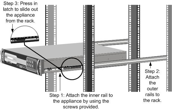
The appliance is shipped with rack-rail hardware. This hardware consists of two inner rails that you attach to the appliance, one on each side, and a rack-rail assembly that you attach to the rack. The following figure illustrates the steps involved in mounting the NetScaler SDX appliance to a rack.
Remove the inner rails from the rail assembly
-
Place the rail assembly on a flat surface.
-
Slide out the inner rail toward the front of the assembly.
-
Press the latch until the inner rail comes all the way out of the rail assembly.
-
Repeat steps 1 through 3 to remove the second inner rail.
Attach the inner rails to the appliance
-
Position the right inner rail behind the handle on the right side of the appliance.
-
Align the holes on the rail with the corresponding holes on the side of the appliance.
-
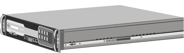
Attach the rail to the appliance with the provided screws: 4 per side for a 1U appliance and 5 per side for a 2U appliance, as shown in the following figure. Figure 1. Attaching inner rails
-
Repeat steps 1 through 3 to install the left inner rail on the other side of the appliance.
Install the rack rails on the rack
-
If you have a round-hole, threaded rack, skip to step 3.
-
Install square nut retainers into the front post and back post of the rack as shown in the following figures. Before inserting a screw, be sure to align the square nut with the correct hole for your 1U or 2U appliance. The three holes are not evenly spaced. Figure 2. Installing Retainers into the Front Rack Posts
 Figure 3. Installing Retainers into the Rear Rack Posts
-
Install the adjustable rail assembly into the rack as shown in the following figures. Use a screw to lock the rear rail flange into the rack. With the screw securing the rail in place, you can optionally remove the latching spring. Figure 4. Installing the Rail Assembly to the Rack

Install the appliance in the rack
-
Align the inner rails, attached to the appliance, with the rack rails.
-
Slide the appliance into the rack rails, keeping the pressure even on both sides.
-
Verify that the appliance is locked in place by pulling it all the way out from the rack. Figure 5. Rack Mounting the Appliance
Watch this quick video about how to rack mount a NetScaler hardware appliance.
Install and remove 1G SFP transceivers
A Small Form-Factor Pluggable (SFP) is a compact transceiver that can operate at speeds of up to 1 gigabit per second and is available in both copper and fiber types. Inserting a 1G SFP copper transceiver converts the 1G SFP port to a 1000BASE-T port. Inserting a 1G SFP fiber transceiver converts the 1G SFP port to a 1000BASE-X port. Auto-negotiation is enabled by default on the 1G SFP port into which you insert your 1G SFP transceiver. When a link between the port and the network is established, the speed and mode are matched on both ends of the cable.
Caution: NetScaler appliances do not support 1G SFP transceivers from vendors other than Citrix Systems. Attempting to install third-party 1G SFP transceivers on your NetScaler appliance voids the warranty.
Insert 1G SFP transceivers into the 1G SFP ports on the front panel of the appliance. Frequent installation and removal of transceivers shortens their life span. Follow the removal procedure carefully to avoid damaging the 1G SFP transceiver or the appliance.
Caution: Do not install the transceivers with the cables attached. Doing so can damage the cable, the connector, or the optical interface of the transceiver.
Install a 1G SFP transceiver
-
Remove the 1G SFP transceiver carefully from its box. Danger: Do not look directly into fiber optic transceivers or cables. They emit laser beams that can damage your eyes.
-
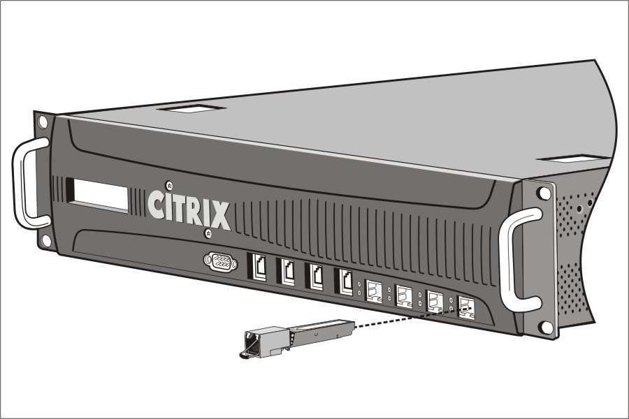
Align the 1G SFP transceiver to the front of the 1G SFP transceiver port on the front panel of the appliance, as shown in the following figure.NoteThe illustration in the following figures might not represent your actual appliance.Figure 6. Installing a 1G SFP transceiver
-
Hold the 1G SFP transceiver between your thumb and index finger and insert it into the 1G SFP transceiver port. Press it in until you hear the transceiver snap into place.
-
Lock the transceiver.
-
Verify that the LED is green and blinks twice, which indicates that the transceiver is functioning correctly.
-
When using a fiber 1G SFP transceiver, do not remove the dust caps attached to the transceiver and the cable until you are ready to insert the cable.
Remove a 1G SFP transceiver
-
Disconnect the cable from the 1G SFP transceiver. If you are using a fiber optic cable, replace the dust cap on the cable before putting it away. Danger: Do not look directly into fiber optic transceivers or cables. They emit laser beams that can damage your eyes.
-
Unlock the 1G SFP transceiver.
-
Hold the 1G SFP transceiver between your thumb and index finger and slowly pull it out of the port.
-
If you are removing a fiber 1G SFP transceiver, replace the dust cap before putting it away.
-
Put the 1G SFP transceiver into its original box or another appropriate container.
Install and remove 10G SFP+ transceivers
A 10-Gigabit Small Form-Factor Pluggable (SFP+) is a compact optical transceiver that can operate at speeds of up to 10 gigabits per second. Autonegotiation is enabled by default on the 10G SFP+ ports into which you insert your 10G SFP+ transceiver. When a link between the port and the network is established, the mode is matched on both ends of the cable and for 10G SFP+ transceivers, the speed is also autonegotiated.
Caution: NetScaler appliances do not support 10G SFP+ transceivers provided by vendors other than Citrix Systems. Attempting to install third-party 10G SFP+ transceivers on your NetScaler appliance voids the warranty.
Insert the 10G SFP+ transceivers into the 10G SFP+ ports on the front panel of the appliance. Frequent installation and removal of transceivers shortens their life span. Follow the removal procedure carefully to avoid damaging the transceiver or the appliance.
Caution: Do not install the transceivers with the cables attached. Doing so can damage the cable, the connector, or the optical interface of the transceiver.
Install a 10G SFP+ transceiver
-
Remove the 10G SFP+ transceiver carefully from its box.Warning: Do not look directly into fiber optic transceivers and cables. They emit laser beams that can damage your eyes.
-
Align the 10G SFP+ transceiver to the front of the 10G SFP+ transceiver port on the front panel of the appliance.
-
Hold the 10G SFP+ transceiver between your thumb and index finger and insert it into the 10G SFP+ transceiver port, pressing it in until you hear the transceiver snap into place.
-
Lock the transceiver.
-
Verify that the LED is green and blinks twice, which indicates that the transceiver is functioning correctly.
-
Do not remove the dust caps attached to the transceiver and cable until you are ready to insert the cable.
Remove a 10G SFP+ transceiver
-
Disconnect the cable from the 10G SFP+ transceiver. Replace the dust cap on the cable before putting it away. Danger: Do not look directly into fiber optic transceivers or cables. They emit laser beams that can damage your eyes.
-
Unlock the 10G SFP+ transceiver.
-
Hold the 10G SFP+ transceiver between your thumb and index finger and slowly pull it out of the port.
-
Replace the dust cap on the transceiver before putting it away.
-
Put the 10G SFP+ transceiver into its original box or another appropriate container.
Connect the cables
When the appliance is securely mounted on the rack, you are ready to connect the cables. Ethernet cables and the optional console cable are connected first. Connect the power cable last.
Warning: Before installing or repairing the appliance, remove all jewelry and other metal objects that might come in contact with power sources or wires. When you touch both a live power source or wire and ground, any metal objects can heat up rapidly and cause burns, set clothing on fire, or fuse the metal object to an exposed terminal.
Connect the Ethernet cables
Ethernet cables connect your appliance to the network. The type of cable you need depends on the type of port used to connect to the network. Use a category 5e or category 6 Ethernet cable with a standard RJ-45 connector on a 10/100/1000BASE-T port or 1G SFP copper transceiver. Use a fiber optic cable with an LC duplex connector with a 1G SFP fiber transceiver, 10G SFP+ transceiver. The type of connector at the other end of the fiber optic cable depends on the port of the device that you are connecting to.
Connect an Ethernet cable to a 10/100/1000BASE-T port or 1G SFP copper transceiver
-
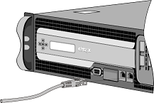
Insert the RJ-45 connector on one end of your Ethernet cable into an appropriate port on the front panel of the appliance, as shown in the following figure. Figure 7. Inserting an Ethernet cable
-
Insert the RJ-45 connector on the other end into the target device, such as a router or switch.
-
Verify that the LED glows amber when the connection is established.
Connect the Ethernet cable to a 1G SFP fiber, 10G SFP+ transceiver
-
Remove the dust caps from the transceiver and cable.
-
Insert the LC connector on one end of the fiber optic cable into the appropriate port on the front panel of the appliance.
-
Insert the connector on the other end into the target device, such as a router or switch.
-
Verify that the LED glows amber when the connection is established.
Connect the Console cable
You can use the console cable to connect your appliance to a computer or terminal, from which you can configure the appliance. Alternatively, you can use a computer connected to the network. Before connecting the console cable, configure the computer or terminal to support VT100 terminal emulation, 9600 baud, 8 data bits, 1 stop bit, parity, and flow control set to NONE. Then connect one end of the console cable to the RS232 serial port on the appliance and the other end to the computer or terminal.
Connect the console cable to a computer or terminal
-
Insert the DB-9 connector at the end of the cable into the console port on the front panel of the appliance, as shown in the following figure. Figure 8. Inserting a console cable
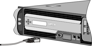 NoteTo use a cable with an RJ-45 converter, insert the optional converter provided into the console port and attach the cable to it.
 -
Insert the RJ-45 connector at the other end of the cable into the serial port of the computer or terminal.
Connect the power cable
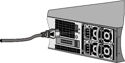
An SDX 8015/8400/8600 appliance has one power cable. All the other appliances come with two power cables, but they can also operate if only one power cable is connected. A separate ground cable is not required, because the three-prong plug provides grounding.
Connect the appliance to the power source
-
Connect one end of the power cable to the power outlet on the back panel of the appliance, next to the power supply, as shown in the following figure. Figure 9. Inserting a power cable
-
Connect the other end of the power cable to a standard 110V/220V power outlet.
-
If a second power supply is provided, repeat steps 1 and 2 to connect the second power supply.NoteSome appliances emit a high-pitched alert if one power supply fails or if you connect only one power cable to the appliance. To silence the alarm, you can press the small red button on the back panel of the appliance.
Switch on the appliance
After you have installed the appliance in a rack and connected the cables, verify that the power cable is properly connected. If you have installed a second power supply, make sure that the second cable is connected to an outlet for a different circuit than the first. After verifying the connections, you are ready to switch on the appliance.
To switch on the appliance
-
Verify that the appliance is connected through a console or Ethernet port. This check ensures that you can configure the appliance after it is switched on.
-
Press the ON/OFF toggle power switch on the back panel of the appliance.
Caution: Be aware of the location of the emergency power off (EPO) switch, so that if an electrical accident occurs you can quickly remove power from the appliance.