
Deploy a NetScaler high-availability pair on Azure with ALB in the floating IP-disabled mode
You can deploy a pair of NetScaler VPX instances with multiple NICs in an active-passive high availability (HA) setup on Azure. Each NIC can contain many IP addresses.
An active-passive deployment requires:
-
An HA Independent Network Configuration (INC) configuration
-
The Azure Load Balancer (ALB) with:
-
Floating IP-enabled mode or Direct Server Return (DSR) mode
-
Floating IP-disabled mode
-
For more information about ALB floating IP options, refer to the Azure documentation.
If you want to deploy a VPX pair in active-passive HA setup on Azure with ALB floating IP enabled, see Configure a high-availability setup with multiple IP addresses and NICs by using PowerShell commands.
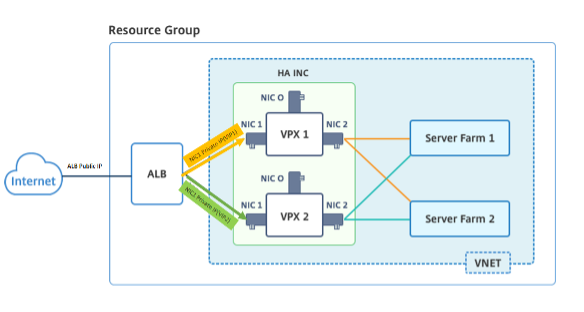
HA deployment architecture with ALB in the floating IP-disabled mode
In an active-passive deployment, the private IP addresses of the client interface of each instance are added as VIP addresses in each VPX instance. Configure in the HA-INC mode with VIP addresses being shared using IPSet and SNIP addresses being instance specific. All traffic goes through the primary instance. The secondary instance is in standby mode until the primary instance fails.
Diagram: Example of an active-passive deployment architecture
Prerequisites
You must be familiar with the following information before deploying a NetScaler VPX instance on Azure.
-
Azure terminology and network details. For more information, see Azure terminology.
-
Working of a NetScaler appliance. For more information, see NetScaler documentation.
-
NetScaler networking. For more information, see the ADC Networking.
-
Azure load balancer and load-balancing rule configuration. For more information, see Azure ALB documentation.
How to deploy a VPX HA pair on Azure with ALB floating IP disabled
Here’s a summary of the HA and ALB deployment steps:
-
Deploy two VPX instances (primary and secondary instances) on Azure.
-
Add client and server NIC on both the instances.
-
Deploy an ALB with load balancing rule whose floating IP mode is disabled.
-
Configure HA settings on both instances by using the NetScaler GUI.
Step 1. Deploy two VPX instances on Azure.
Create two VPX instances by following these steps:
-
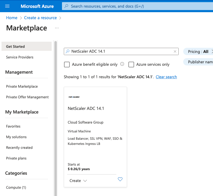
Select the NetScaler version from Azure Marketplace (in this example, NetScaler release 13.1 is used).
-
Select the required ADC licensing mode, and click Create.
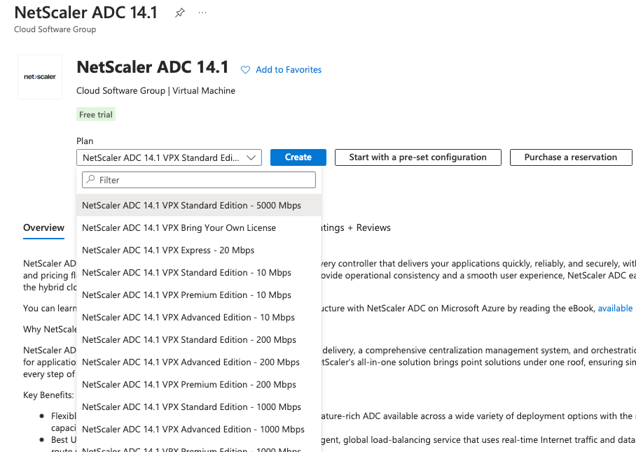 The Create a virtual machine page opens.
 -
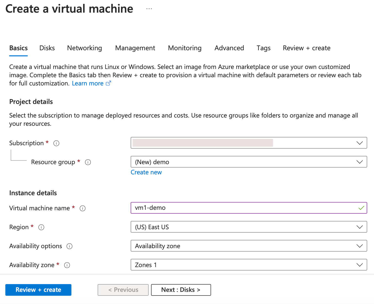
Complete the required details in each tab: Basics, Disks, Networking, Management, Monitoring, Advanced, and Tags, for a successful deployment.
-
In the Networking tab, create a new Virtual network with 3 subnets, one each for: management, client, and server NICs. Otherwise, you can also use an existing Virtual network. Management NIC is created during the VM deployment. Client and server NICs are created and attached after the VM is created. For the NIC network security group, you can do one of the following:
-
Select Advanced and use an existing network security group that suits your requirements.
-
Select Basic and select the required ports.
Note:You can also change the network security group settings after the VM deployment is completed.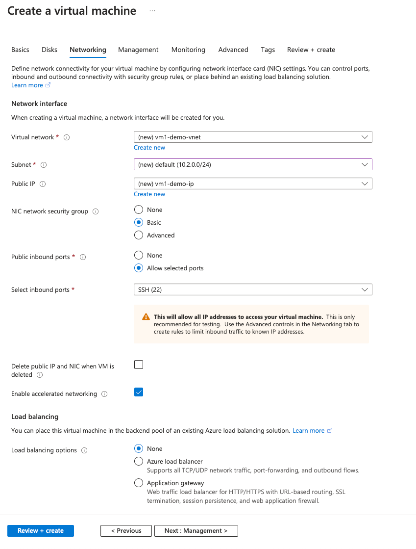
-
-
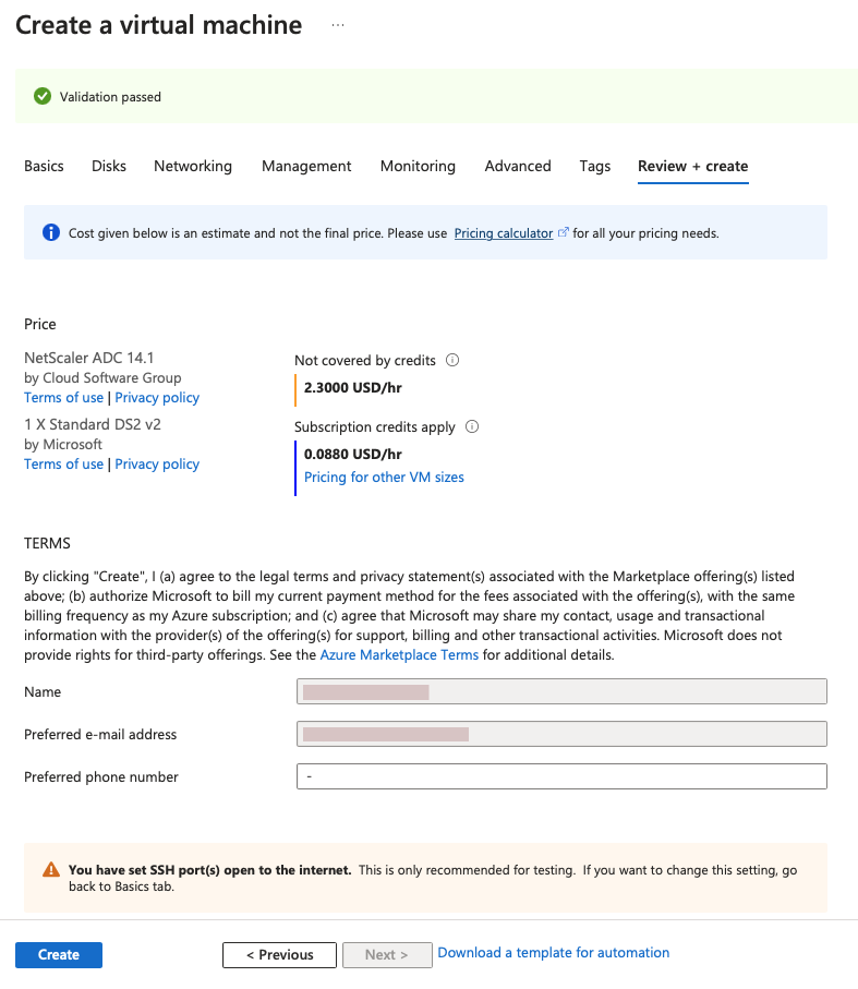
Click Next: Review + create >.After the validation is successful, review the basic settings, VM configurations, network and additional settings, and click Create.
-
After the deployment is complete, Click Go to Resource to see the configuration details.
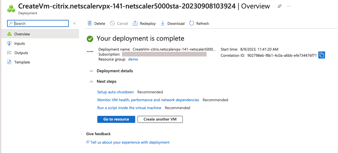 Similarly, deploy a second NetScaler VPX instance.
Step 2. Add client and server NICs on both instances.
Note:
To attach more NICs, you must first stop the VM. In the Azure portal, select the VM that you want to stop. In the Overview tab, click Stop. Wait for Status to show as Stopped.
To add a client NIC on the primary instance, follow these steps:
-
Navigate to Networking > Attach Network Interface.You can select an existing NIC or create and attach a new interface.
-
For the NIC Network Security Group, you can use an existing network security group by selecting Advanced or create one by selecting Basic.
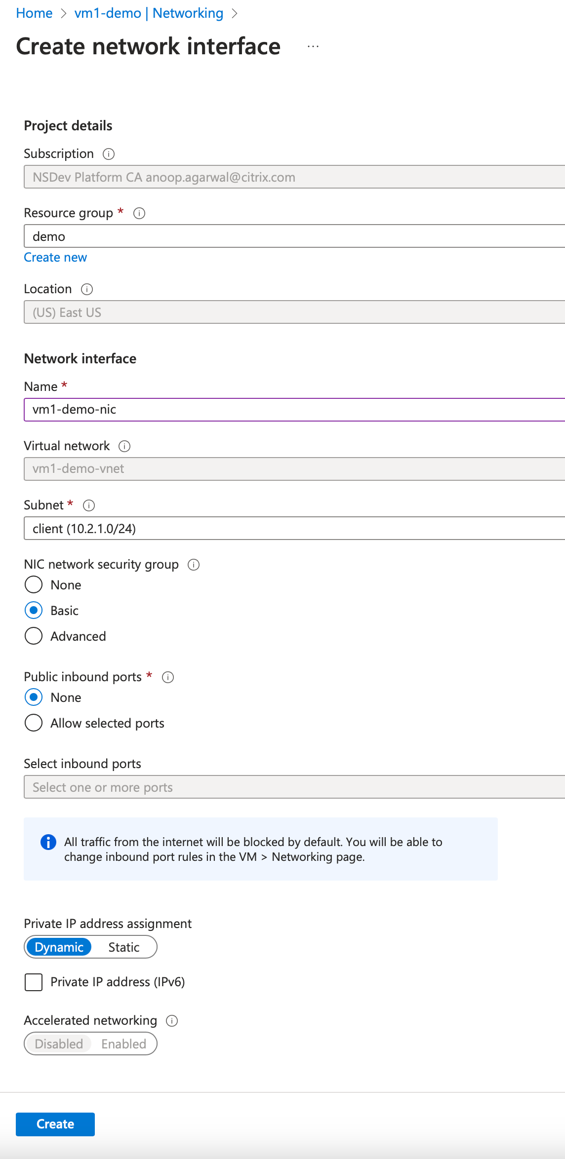
To add a server NIC, follow the same steps as for adding a client NIC.
The NetScaler VPX instance has all three NICs (management NIC, client NIC, and server NIC) attached.
Repeat the preceding steps for adding NICs on the secondary instance.
After you create and attach NICs on both the instances, restart both the instances by going to Overview > Start.
Note:
You must allow traffic through the port in client NIC inbound rule, which is used later to create a load balancing virtual server while configuring the NetScaler VPX instance.
Step 3. Deploy an ALB with load balancing rule whose floating IP mode is disabled.
To start the configuration of ALB, follow these steps:
-
Go to the Load balancers page and click Create.
-
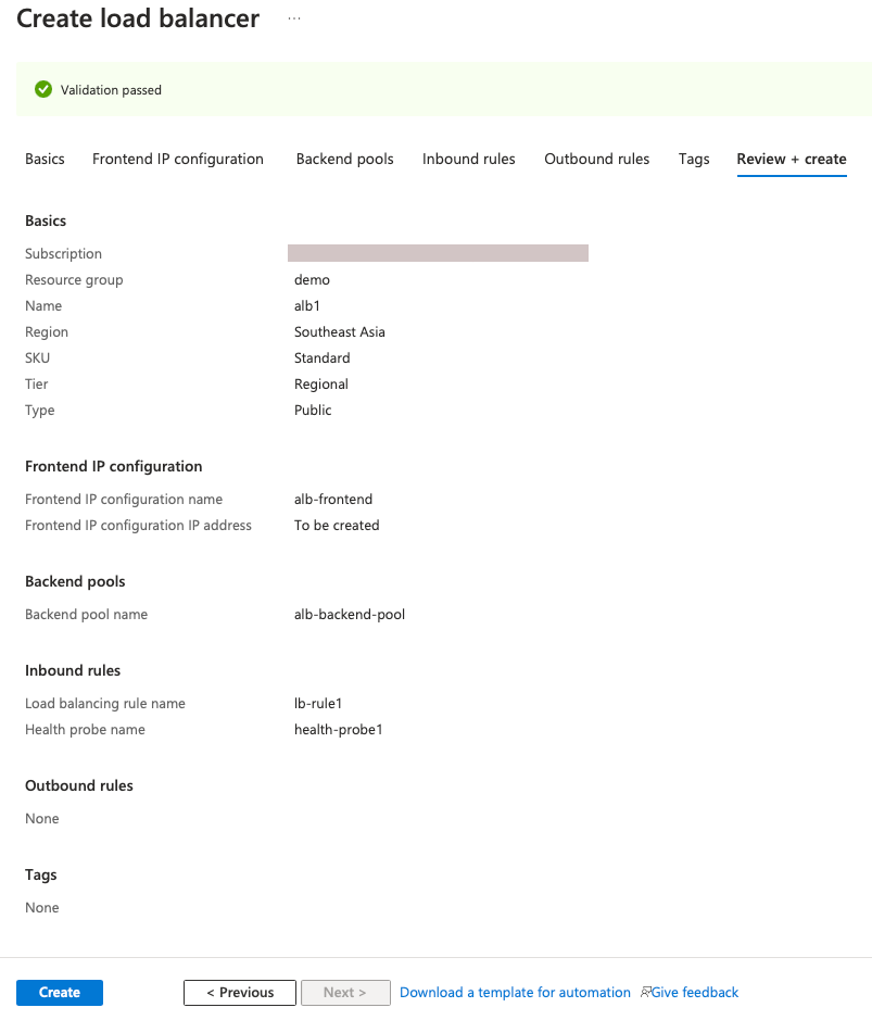
In the Create load balancer page, provide the details as required.In the following example, we deploy a regional public load balancer of Standard SKU.
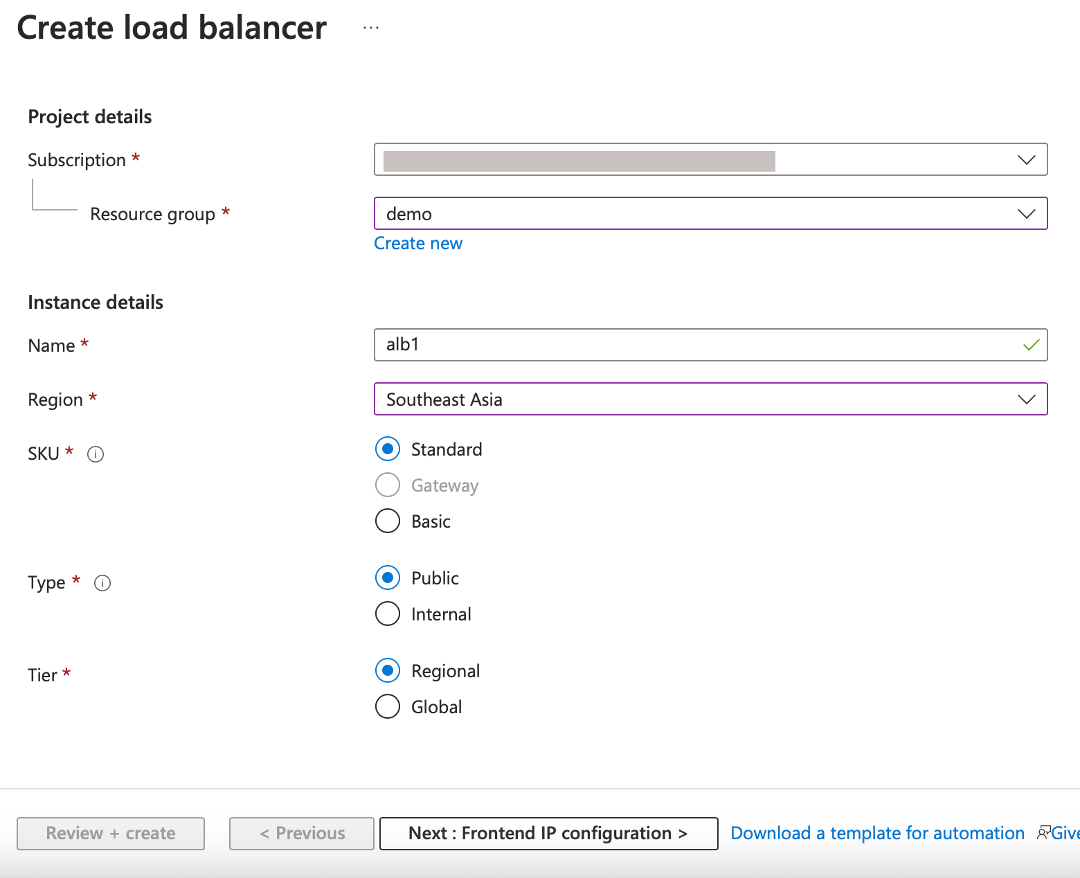 Note:All public IPs attached to the NetScaler VMs must have the same SKU as that of ALB. For more information about ALB SKUs, see the Azure Load Balancer SKUs' documentation.
 -
In the Frontend IP configuration tab, either create an IP address or use an existing IP address.
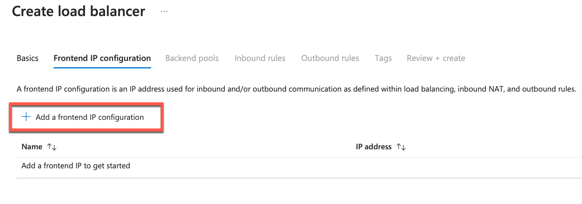
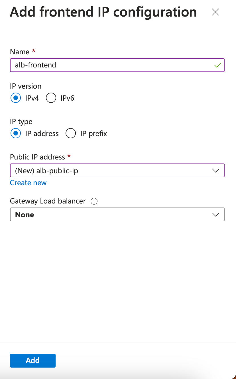
-
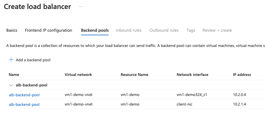
In the Backend pools tab, select NIC-based backend pool configuration, and add the client NICs of both the NetScaler VMs.
-
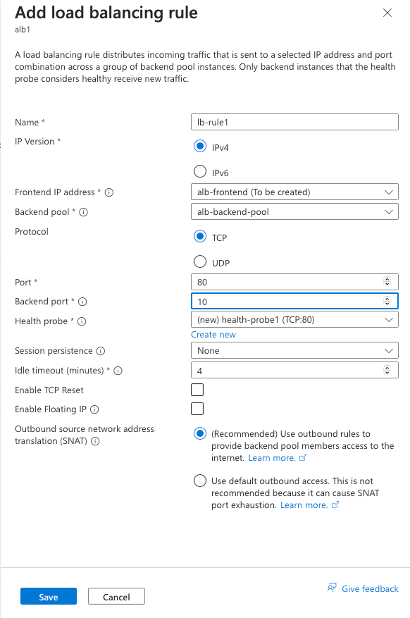
In Inbound rules tab, click Add a Load balancing rule, and provide the frontend IP address and backend pool created in the previous steps. Select the protocol and port based on your requirement. Create or use an existing health probe. The floating IP option must be set as Disabled.
-
Click Review + Create. After the validation is passed, click Create.
Step 4. Configure HA settings on both NetScaler VPX instances by using the NetScaler GUI.
After you have created the NetScaler VPX instances on Azure, you can configure HA by using the NetScaler GUI.
Step 1. Set up high availability in INC mode on both the instances.
On the primary instance, do the following steps:
-
Log on to the instance with user name
nsrootand password provided while deploying the instance. -
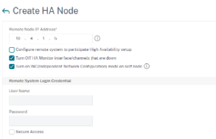
Navigate to Configuration > System > High Availability > Nodes, and click Add.
-
In the Remote Node IP address field, enter the private IP address of the management NIC of the secondary instance, for example: 10.4.1.5.
-
Select the Turn on INC (Independent Network Configuration) mode on self node check box.
-
Click Create.
On the secondary instance, do the following steps:
-
Log on to the instance with user name
nsrootand password provided while deploying the instance. -
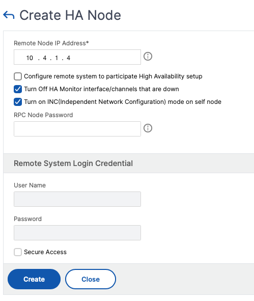
Navigate to Configuration > System > High Availability > Nodes, and click Add.
-
In the Remote Node IP address field, enter the private IP address of the management NIC of the primary instance, for example: 10.4.1.4.
-
Select the Turn on INC (Independent Network Configuration) mode on self node check box.
-
Click Create.
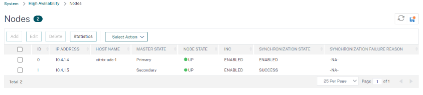
Before you proceed further, ensure that the Synchronization state of the secondary instance is shown as SUCCESS in the Nodes page.
Note:
Now the secondary instance has the same log-on credentials as the primary instance.
Step 2. Add virtual IP address and subnet IP address on both the instances.
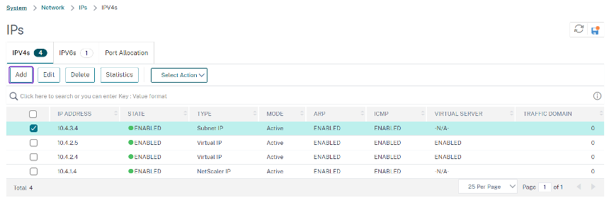
On the primary instance, perform the following steps:
-
Navigate to System > Network > IPs > IPv4s, and click Add.
-
Add a primary VIP address by following these steps:
-
Enter the private IP address of the client NIC of the primary instance and netmask configured for the client subnet in the VM instance.
-
In the IP Type field, select Virtual IP from the drop-down menu.
-
Click Create.
-
-
Add a primary SNIP address by following these steps:
-
Enter the internal IP address of the server NIC of the primary instance, and netmask configured for the server subnet in the primary instance.
-
In the IP Type field, select Subnet IP from the drop-down menu.
-
Click Create.
-
-
Add a secondary VIP address by following these steps:
-
Enter the internal IP address of the client NIC of the secondary instance, and netmask configured for the client subnet in the VM instance.
-
In the IP Type field, select Virtual IP from the drop-down menu.
-
Click Create.
-
On the secondary instance, perform the following steps:
-
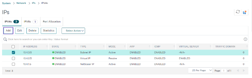
Navigate to System > Network > IPs > IPv4s, and click Add.
-
Add a secondary VIP address by following these steps:
-
Enter the internal IP address of the client NIC of the secondary instance, and netmask configured for the client subnet in the VM instance.
-
In the IP Type field, select Virtual IP from the drop-down menu.
-
-
Add a secondary SNIP address by following these steps:
-
Enter the internal IP address of the server NIC of the secondary instance, and netmask configured for the server subnet in the secondary instance.
-
In the IP Type field, select Subnet IP from the drop-down menu.
-
Click Create.
-
Step 3. Add IP set and bind IP set to the secondary VIP on both the instances.
On the primary instance, do the following steps:
-
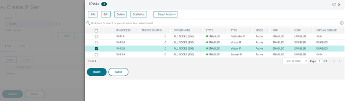
Navigate to System > Network > IP Sets > Add.
-
Add an IP set name and click Insert.
-
From the IPV4s page, select the virtual IP (secondary VIP) and click Insert.
-
Click Create to create the IP set.
On the secondary instance, do the following steps:
-
Navigate to System > Network > IP Sets > Add.
-
Add an IP set name and click Insert.
-
From the IPv4s page, select the virtual IP (secondary VIP) and click Insert.
-
Click Create to create the IP set.
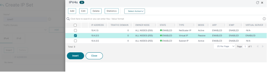
Note:
The IP set name must be the same on both the primary and secondary instances.
Step 4. Add a load balancing virtual server on the primary instance.
-
Navigate to Configuration > Traffic Management > Load Balancing > Virtual Servers > Add.
-
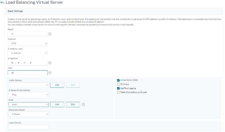
Add the required values for Name, Protocol, IP Address Type (IP Address), IP address (primary VIP), and Port.
-
Click More. Navigate to IP Range IP Set Settings, select IPset from the drop-down menu, and provide the IPset created in Step 3.
-
Click OK to create the load balancing virtual server.
Step 5. Add a service or service group on the primary instance.
-
Navigate to Configuration > Traffic Management > Load Balancing > Services > Add.
-
Add the required values for Service Name, IP Address, Protocol and Port, and click OK.
Step 6. Bind the service or service group to the load balancing virtual server on the primary instance.
-
Navigate to Configuration > Traffic Management > Load Balancing > Virtual Servers.
-
Select the load balancing virtual server configured in Step 4, and click Edit.
-
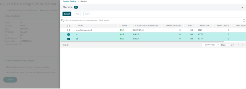
In the Service and Service Groups tab, click No Load Balancing Virtual Server Service Binding.
-
Select the service configured in the Step 5, and click Bind.
Step 7. Save the configuration.
Otherwise, all the configuration is lost after a reboot or if there is an instant restart.
Step 8. Verify the configuration.
Make sure that the ALB frontend IP address is reachable after a failover.
-
Copy the ALB frontend IP address.
-
Paste the IP address on browser and make sure that the back-end servers are reachable.
-
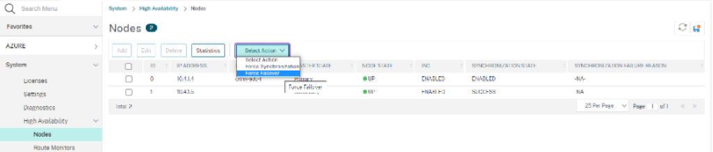
On the primary instance, perform failover:From NetScaler GUI, navigate to Configuration > System > High Availability > Action > Force Failover.
-
Make sure that back-end servers are reachable after failover through ALB frontend IP used earlier.