
Deploy {{page.netscaler-cpx-short}} in a Multi-Host Network
A {{page.netscaler-cpx-short}} instance in a multi-host network may be configured in a production deployment in the datacenter where it provides load balancing functions. It can further provide monitoring functions and analytics data.
In a multi-host network, the {{page.netscaler-cpx-short}} instances, backend servers, and the clients are deployed on different hosts. You can use multi-host topologies in production deployments where the {{page.netscaler-cpx-short}} instance load balances a set of container-based applications and servers or even physical servers.
Topology 1: {{page.netscaler-cpx-short}} and Backend Servers on Same Host; Client on a Different Network
In this topology, the {{page.netscaler-cpx-short}} instance and the database servers are provisioned on the same Docker host, but the client traffic originates from elsewhere on the network. This topology might be used in a production deployment where the {{page.netscaler-cpx-short}} instance load balances a set of container-based applications or servers.
The following diagram illustrates this topology.
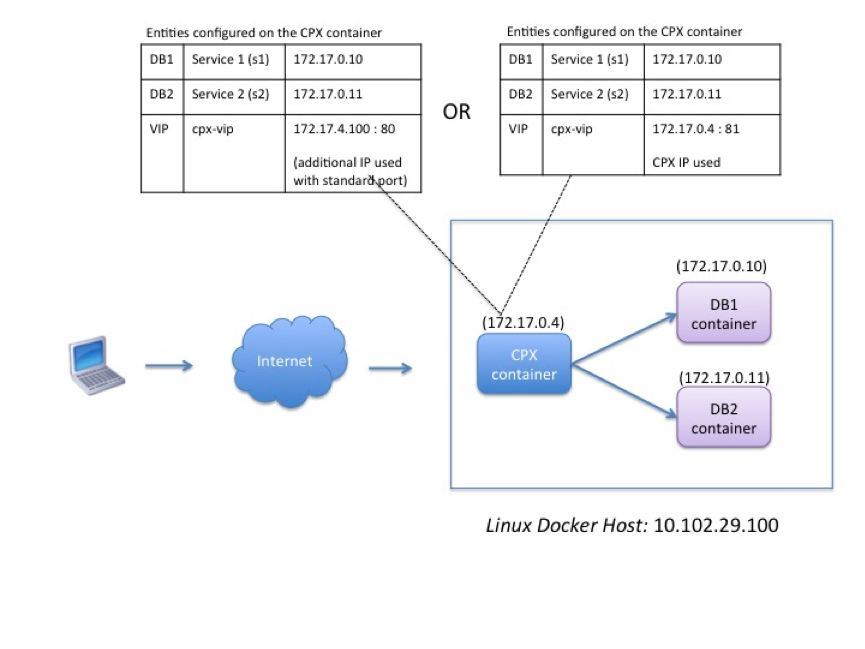
In this example, the {{page.netscaler-cpx-short}} instance (172.17.0.4) and the two servers, DB1 (172.17.0.10) and DB2 (172.17.0.11) are provisioned on the same Docker host with IP address 10.102.29.100. The client resides elsewhere on the network.
The client requests originating from the Internet are received on the VIP configured on the {{page.netscaler-cpx-short}} instance, which then distributes the requests across the two servers.
There are two methods you can use to configure this topology:
Method 1: Using an additional IP address and standard port for the VIP
-
Configure the VIP on the {{page.netscaler-cpx-short}} container by using an additional IP address.
-
Configure an additional IP address for the Docker host.
-
Configure NAT rules to forward all traffic received on the Docker host’s additional IP address to the VIP’s additional IP address.
-
Configure the two servers as services on the {{page.netscaler-cpx-short}} instance.
-
Finally, bind the services to the VIP.
Note that in this example configuration, the 10.x.x.x network denotes a public network.
To configure this example scenario, run the following commands either by using the Jobs feature in NetScaler® MAS or by using NITRO APIs:
add service s1 172.17.0.10 HTTP 80
 add service s2 172.17.0.11 HTTP 80
 add lb vserver cpx-vip HTTP 172.17.4.100 80
 bind lb vserver cpx-vip s1
 bind lb vserver cpx-vip s2
Configure an additional public IP address for the Docker host and a NAT rule by running the following commands at the Linux shell prompt:
ip addr add 10.102.29.103/24 dev eth0
 iptables -t nat -A PREROUTING -p ip  -d 10.102.29.103 -j DNAT --to-destination 172.17.4.100
Method 2: Using the {{page.netscaler-cpx-short}} IP address for the VIP and by configuring port mapping:
-
Configure the VIP and the two services on the {{page.netscaler-cpx-short}} instance. Use a non-standard port, 81, with the VIP.
-
Bind the services to the VIP.
-
Configure a NAT rule to forward all traffic received on port 50000 of the Docker host to the VIP and port 81.
To configure this example scenario, run the following command at the Linux shell prompt while creating the {{page.netscaler-cpx-short}} container on all three Docker hosts:
docker run -dt -p 22 -p 80 -p 161/udp -p 50000:81 --ulimit core=-1 --privileged=true cpx:6.2
After the {{page.netscaler-cpx-short}} instance is provisioned, run the following commands either by using the Jobs feature in NetScaler MAS or by using NITRO APIs:
add service s1 172.17.0.10 http 80
 add service s2 172.17.0.11 http 80
 add lb vserver cpx-vip HTTP 172.17.0.4 81
 bind lb vserver cpx-vip s1
 bind lb vserver cpx-vip s2
Note:
If you have not configured port mapping during provisioning of the {{page.netscaler-cpx-short}} instance, then configure a NAT rule by running the following commands at the Linux shell prompt:
iptables -t nat -A PREROUTING -p tcp -m addrtype --dst-type LOCAL -m tcp --dport 50000 -j DNAT --to-destination 172.17.0.4:81
Topology 2: {{page.netscaler-cpx-short}} with Physical Servers and Client
In this topology, only the {{page.netscaler-cpx-short}} instance is provisioned on a Docker host. The client and the servers are not container-based and reside elsewhere on the network.
In this environment, you can configure the {{page.netscaler-cpx-short}} instance to load balance traffic across the physical servers.
The following figure illustrates this topology.
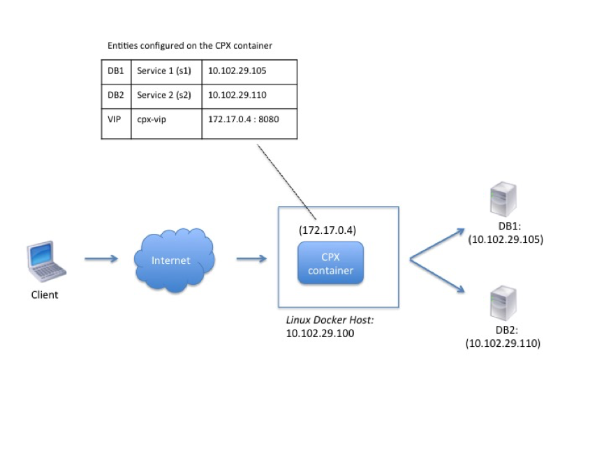
In this example, the {{page.netscaler-cpx-short}} container (172.17.0.4) sits between the client and the physical servers acting as a proxy. The servers, DB1 (10.102.29.105) and DB2 (10.102.29.110), reside outside a Docker host on the network. The client request originates from the Internet and is received on the {{page.netscaler-cpx-short}}, which distributes it across the two servers.
To enable this communication between the client and the servers through {{page.netscaler-cpx-short}}, you have to first configure port mapping while creating the {{page.netscaler-cpx-short}} container. Then, configure the two services on the {{page.netscaler-cpx-short}} container to represent the two servers. And finally, configure a virtual server by using the {{page.netscaler-cpx-short}} IP address and the non-standard mapped HTTP port 8080.
Note that in the example configuration, the 10.x.x.x network denotes a public network.
To configure this example scenario, run the following command at the Linux shell prompt while creating the {{page.netscaler-cpx-short}} container:
docker run -dt -p 22 -p 80 -p 161/udp -p 8080:8080 --ulimit core=-1 --privileged=true cpx:6.2
Then, run the following commands either by using the Jobs feature in NetScaler MAS or by using NITRO APIs:
add service s1 HTTP 10.102.29.105 80
 add service s2 HTTP 10.102.29.110 80
 add lb vserver cpx-vip HTTP 172.17.0.4 8080
 bind lb vserver cpx-vip s1
 bind lb vserver cpx-vip s2
Topology 3: {{page.netscaler-cpx-short}} and Servers Provisioned on Different Hosts
In this topology, the {{page.netscaler-cpx-short}} instance and the database servers are provisioned in different Docker hosts, and the client traffic originates from the Internet. This topology might be used in a production deployment where the {{page.netscaler-cpx-short}} instance load balances a set of container-based applications or servers.
The following diagram illustrates this topology.
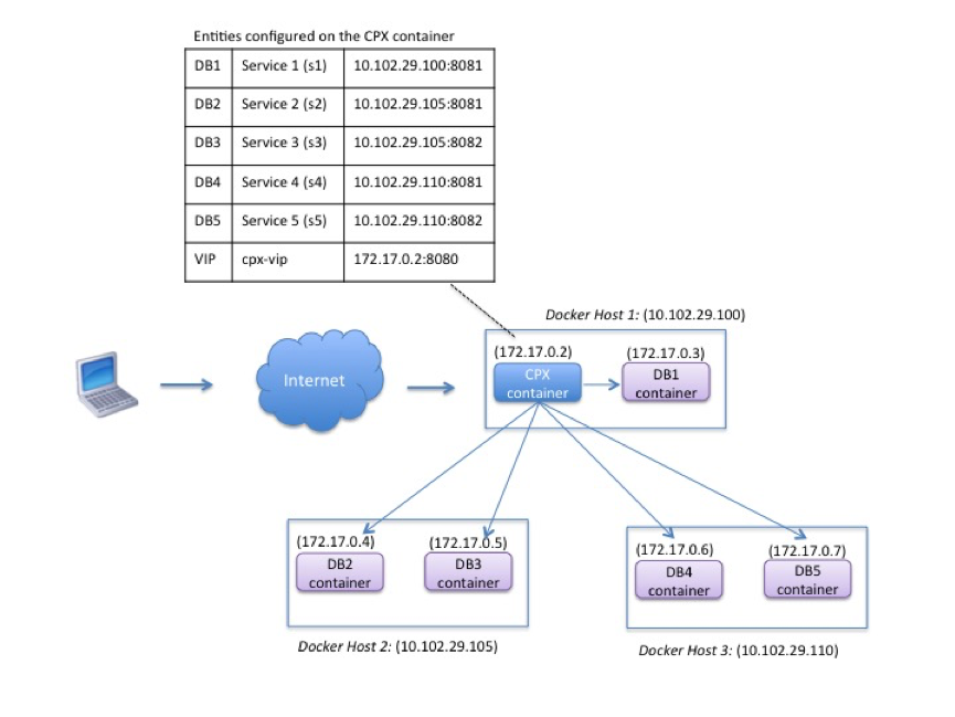
In this example, the {{page.netscaler-cpx-short}} instance and a server (DB1) are provisioned on the same Docker host with IP address 10.102.29.100. Four other servers (DB2, DB3, DB4, and DB5) are provisioned on two different Docker hosts, 10.102.29.105 and 10.102.29.110.
The client requests originating from the Internet are received on the {{page.netscaler-cpx-short}} instance, which then distributes the requests across the five servers. To enable this communication, you must configure the following:
-
Set port mapping while creating your {{page.netscaler-cpx-short}} container. In this example, this means that you have to forward port 8080 on the container to port 8080 on the host. When the client request arrives on port 8080 of the host, it maps to port 8080 of the CPX container.
-
Configure the five servers as services on the {{page.netscaler-cpx-short}} instance. You have to use a combination of the respective Docker host IP address and mapped port to set these services.
-
Configure a VIP on the {{page.netscaler-cpx-short}} instance to receive the client request. This VIP should be represented by the {{page.netscaler-cpx-short}} IP address and port 8080 that was mapped to port 8080 of the host.
-
Finally, bind the services to the VIP.
Note that in the example configuration, the 10.x.x.x network denotes a public network.
To configure this example scenario, run the following command at the Linux shell prompt while creating the {{page.netscaler-cpx-short}} container:
docker run -dt -p 22 -p 80 -p 161/udp -p 8080:8080 --ulimit core=-1 --privileged=true cpx:6.2
Run the following commands either by using the Jobs feature in NetScaler MAS or by using NITRO APIs:
add service s1 10.102.29.100 HTTP 8081
 add service s2 10.102.29.105 HTTP 8081
 add service s3 10.102.29.105 HTTP 8082
 add service s4 10.102.29.110 HTTP 8081
 add service s5 10.102.29.110 HTTP 8082
 add lb vserver cpx-vip HTTP 172.17.0.2 8080
 bind lb vserver cpx-vip s1
 bind lb vserver cpx-vip s2
 bind lb vserver cpx-vip s3
 bind lb vserver cpx-vip s4
 bind lb vserver cpx-vip s5